autocad 3d drawing in tamil
Drawing Objects
Introduction
This tutorial is designed to bear witness you how all of the AutoCAD Describe commands work. If you just need information apace, use the QuickFind toolbar below to become straight to the command yous want or select a topic from the contents listing above. Non all of the Draw commands that appear on the Draw toolbar are covered in this tutorial. Blocks, Hatch and Text for example are all tutorial topics in their own right!
| | | | | | | | | | | | | | | | | |
The Depict commands tin can exist used to create new objects such equally lines and circles. Most AutoCAD drawings are equanimous purely and simply from these basic components. A adept understanding of the Draw commands is fundamental to the efficient utilise of AutoCAD.
The sections below cover the about frequently used Describe commands such equally Line, Polyline and Circle every bit well as the more advanced commands like Multiline and Multiline Fashion. As a newcomer to AutoCAD, you may wish to skip the more than advanced commands in society to properly master the basics. You can always return to this tutorial in the future when you are more than confident.
In common with most AutoCAD commands, the Depict commands can be started in a number of ways. Command names or short-cuts tin be entered at the keyboard, commands can be started from the Draw pull-down menu, shown on the correct or from the Draw toolbar. The method you use is dependent upon the type of piece of work you are doing and how experienced a user you are. Don't worry too much near this, just apply any method feels easiest or most convenient at the time. Your cartoon technique will improve over time and with experience so don't expect to be working very quickly at showtime.
If you are working with the pull-down menus, it is worth considering the visual syntax that is mutual to all pull-downs used in the Windows operating organization. For example, a small pointer like and so "![]() " adjacent to a bill of fare item means that the item leads to a sub-carte du jour that may contain other commands or command options. An ellipsis, "…" after a menu item means that the item displays a dialogue box. These piffling visual clues will help you to work more effectively with menus because they tell y'all what to expect and aid to avoid surprises for the newcomer.
" adjacent to a bill of fare item means that the item leads to a sub-carte du jour that may contain other commands or command options. An ellipsis, "…" after a menu item means that the item displays a dialogue box. These piffling visual clues will help you to work more effectively with menus because they tell y'all what to expect and aid to avoid surprises for the newcomer.
Top of page
Lines
Lines are probably the almost simple of AutoCAD objects. Using the Line command, a line can be drawn between any two points picked inside the cartoon expanse. Lines are usually the kickoff objects you lot will want to depict when starting a new drawing because they can be used as "structure lines" upon which the residuum of your drawing will be based. Never forget that creating drawings with AutoCAD is not and then dissimilar from creating drawings on a drawing board. Many of the bones drawing methods are the same.
Anyone familiar with mathematics will know that lines fatigued between points are often called vectors. This terminology is used to describe the type of drawings that AutoCAD creates. AutoCAD drawings are generically referred to equally "vector drawings". Vector drawings are extremely useful where precision is the virtually important criterion considering they retain their accuracy irrespective of scale.
Top of page
The Line Command
| Toolbar | Draw | | |
| Pull-downward | |||
| Keyboard | LINE | short-cut | L |
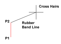 With the Line control you lot tin depict a unproblematic line from 1 point to some other. When yous option the starting time point and motion the cross-hairs to the location of the 2nd point yous will see a prophylactic band line which shows you where the line will exist drawn when the second point is picked. Line objects take two ends (the first point and the last point). You can continue picking points and AutoCAD volition describe a straight line between each picked bespeak and the previous point. Each line segment drawn is a separate object and tin exist moved or erased as required. To end this command, simply striking the
 ![]() central on the keyboard.
central on the keyboard.
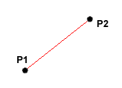
Command Sequence
Command: LINE
Specify starting time point: (option P1)
Specify adjacent point or [Disengage]: (choice P2)
Specify adjacent point or [Undo]: ![]() (to end)
(to end)
You lot tin can also draw lines past entering the co-ordinates of their terminate points at the command prompt rather than picking their position from the screen. This enables y'all to depict lines that are off screen, should you desire to. (See Using Co-ordinates for more details). You can also depict lines using something called direct distance entry. See the Direct Distance Entry tutorial for details.
Acme of page
The Construction Line Command
| Toolbar | Draw | | |
| Pull-down | |||
| Keyboard | XLINE | short-cut | XL |
The Construction Line control creates a line of infinite length which passes through ii picked points. Construction lines are very useful for creating construction frameworks or grids within which to design.
Construction lines are non ordinarily used every bit objects in finished drawings, information technology is usual, therefore, to depict all your construction lines on a split layer which will be turned off or frozen prior to printing. Meet the Object Backdrop tutorial to find out how to create new layers. Because of their nature, the Zoom Extents command option ignores construction lines.
Command Sequence
Command: XLINE
Specify a bespeak or [Hor/Ver/Ang/Bisect/Commencement]: (selection a point)
Specify through point: (pick a 2d point)
Specify through point: ![]() (to cease or pick some other point)
(to cease or pick some other point)
You may notice that in that location are a number of options with this command. For example, the "Hor" and "Ver" options tin can be used to draw construction lines that are truly horizontal or vertical. In both these cases, only a unmarried pick point is required because the management of the line is predetermined. To utilise a control option, just enter the capitalised part of the option name at the control prompt. Follow the command sequence below to come across how you would draw a construction line using the Horizontal option.
Control Sequence
Command: XLINE
Hor/Ver/Ang/Bifurcate/Start/<From point>: H ![]()
Through point: (pick a signal to position the line)
Through betoken: ![]() (to end or selection a point for another horizontal line)
(to end or selection a point for another horizontal line)
Tiptop of page
The Ray Command
The Ray command creates a line similar to a construction line except that it extends infinitely in only one direction from the first selection point. The management of the Ray is adamant past the position of the second pick point.
Command Sequence
Control: RAY
Specify start betoken: (pick the start bespeak)
Specify through signal: (pick a second point to determine direction)
Specify through betoken: ![]() (to end or pick another bespeak)
(to end or pick another bespeak)
Superlative of page
The Polyline Family
Polylines differ from lines in that they are more than complex objects. A single polyline can be equanimous of a number of directly-line or arc segments. Polylines tin can besides be given line widths to make them appear solid. The illustration below shows a number of polylines to give you an thought of the flexibility of this type of line.

You may be wondering, if Polylines are and then useful, why bother using ordinary lines at all? There are a number of answers to this question. The nearly often given answer is that because of their complexity, polylines use upward more disk space than the equivalent line. As it is desirable to keep file sizes equally small as possible, it is a good idea to use lines rather than polylines unless you have a detail requirement. You will also find, equally y'all work with AutoCAD that lines and polylines are operationally different. Sometimes information technology is easier to work with polylines for certain tasks and at other times lines are best. You volition quickly learn the pros and cons of these two sorts of line when you brainstorm drawing with AutoCAD.
Top of page
The Polyline Command
| Toolbar | Draw | | |
| Pull-downwards | |||
| Keyboard | PLINE | brusque-cutting | PL |
The Polyline or Pline control is similar to the line command except that the resulting object may be composed of a number of segments which form a single object. In addition to the 2 ends a polyline is said to have vertices (singular vertex) where intermediate line segments bring together. In practice the Polyline control works in the same manner as the Line command assuasive you to choice as many points as you like. Again, just hitting ![]() to end. As with the Line control, you likewise have the selection to automatically close a polyline terminate to end. To practice this, type C to utilise the close option instead of hit
to end. As with the Line control, you likewise have the selection to automatically close a polyline terminate to end. To practice this, type C to utilise the close option instead of hit ![]() . Follow the command sequence below to run across how this works.
. Follow the command sequence below to run across how this works.
Command Sequence
Command: PLINE
Specify get-go indicate: (pick P1)
Current line-width is 0.0000
Specify next point or [Arc/Halfwidth/Length/Undo/Width]: (selection P2)
Specify next bespeak or [Arc/Close/Halfwidth/Length/Undo/Width]: (pick P3)
Specify next point or [Arc/Close/Halfwidth/Length/Undo/Width]: (option P4)
Specify next point or [Arc/Shut/Halfwidth/Length/Disengage/Width]: (option P5)
Specify next point or [Arc/Close/Halfwidth/Length/Undo/Width]: ![]() (or C to close)
(or C to close)
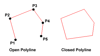 In the illustration on the correct, the effigy on the left was created past striking the
 ![]() key after the fifth point was picked. The figure on the right demonstrates the effect of using the Shut option.
key after the fifth point was picked. The figure on the right demonstrates the effect of using the Shut option.
It is worth while taking some time to familiarise yourself with the Polyline command equally it is an extremely useful command to know. Try experimenting with options such equally Arc and Width and encounter if y'all can create polylines like the ones in the analogy above. The Undo option is peculiarly useful. This allows y'all to unpick polyline vertices, 1 at a time and then that you tin hands right mistakes.
Polylines can be edited after they are created to, for example, modify their width. You can do this using the PEDIT command, from the pull-downward menu.
Top of folio
The Rectangle Control
| Toolbar | Draw | | |
| Pull-downwards | |||
| Keyboard | RECTANGLE | short-cuts | REC, RECTANG |
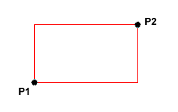 The Rectangle command is used to describe a rectangle whose sides are vertical and horizontal. The position and size of the rectangle are divers by picking two diagonal corners. The rectangle isn't actually an AutoCAD object at all. Information technology is, in fact, just a closed polyline which is automatically fatigued for you.
Control Sequence
Command: RECTANG
Specify first corner point or [Chamfer/Acme/Fillet/Thickness/Width]: (pick P1)
Specify other corner betoken or [Dimensions]: (pick P2)
The Rectangle control too has a number of options. Width works in the same way as for the Polyline control. The Chamfer and Fillet options have the same effect as the Chamfer and Fillet commands, meet the Modifying Objects tutorial for details. Elevation and Thickness are 3D options.
Notice that, instead of picking a second betoken to draw the rectangle, y'all have the selection of entering dimensions. Say y'all wanted to draw a rectangle 20 drawing units long and ten drawing units broad. The command sequence would look like this:
Command Sequence
Command: RECTANG
Specify first corner point or [Chamfer/Peak/Fillet/Thickness/Width]: (pick a bespeak)
Specify other corner point or [Dimensions]: D
Specify length for rectangles <0.0000>: twenty
Specify width for rectangles <0.0000>: 10
Specify other corner point or [Dimensions]: (selection a point to fix the orientation)
This method provides a proficient culling to using relative cartesian co-ordinates for determining length and width. See the Using Co-ordinates tutorial for more details.
Top of folio
The Polygon Command
| Toolbar | Draw | | |
| Pull-down | |||
| Keyboard | POLYGON | short-cut | POL |
The Polygon command can be used to draw whatsoever regular polygon from 3 sides up to 1024 sides. This command requires four inputs from the user, the number of sides, a pick point for the middle of the polygon, whether you desire the polygon inscribed or circumscribed and and so a option signal which determines both the radius of this imaginary circle and the orientation of the polygon. The polygon command creates a airtight polyline in the shape of the required polygon.
This command also allows you to define the polygon by inbound the length of a side using the Border option. You lot can also control the size of the polygon by entering an exact radius for the circle. Follow the command sequence below to see how this command works.
Control Sequence
Command: POLYGON
Enter number of sides <4>: 5 ![]()
Specify center of polygon or [Edge]: (pick P1 or type Due east to define by border length)
Enter an option [Inscribed in circumvolve/Confining about circle] <I>: ![]() (to take the inscribed default or type C for circumscribed)
(to take the inscribed default or type C for circumscribed)
Specify radius of circle: (pick P2 or enter exact radius)
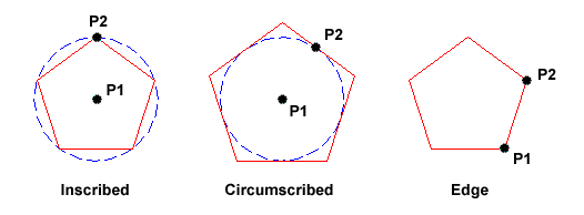
In the illustration higher up, the polygon on the left is inscribed (within the circle with the polygon vertexes touching it), the one in the eye is circumscribed (exterior the circumvolve with the polyline edges tangential to it) and the ane on the right is defined by the length of an edge.
Elevation of page
The Donut Command
| Toolbar | custom | | |
| Pull-down | |||
| Keyboard | DONUT | short-cut | DO |
This command draws a solid donut shape, actually it'south just a closed polyline consisting of two arc segments which have been given a width. AutoCAD asks you to define the inside diameter i.e. the diameter of the hole and so the outside diameter of the donut.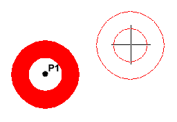 The donut is then drawn in outline and yous are asked to pick the centre point in order to position the donut. You lot can continue picking centre points to describe more donuts or you can hit
 ![]() to stop the control. Surprisingly, donuts are constructed from single airtight polylines composed of two arc segments which have been given a width. Fortunately AutoCAD works all this out for you lot, and so all you see is a donut.
to stop the control. Surprisingly, donuts are constructed from single airtight polylines composed of two arc segments which have been given a width. Fortunately AutoCAD works all this out for you lot, and so all you see is a donut.
Command Sequence
Control: DONUT
Specify inside diameter of donut <0.5000>: (choice any two points to ascertain a diameter or enter the exact length)
Specify outside diameter of donut <1.0000>: (selection any two points to define a bore or enter the verbal length)
Specify middle of donut or <exit>: (selection P1)
Specify center of donut or <leave>: ![]() (to cease or keep to pick for more doughnuts)
(to cease or keep to pick for more doughnuts)
Every bit an alternative to picking two points or entering a value for the diameters, yous could just hit ![]() to accept the default value. Near AutoCAD commands that require user input accept default values. They always appear in triangular brackets like this <default value>.
to accept the default value. Near AutoCAD commands that require user input accept default values. They always appear in triangular brackets like this <default value>.
Curiously enough AutoCAD doesn't seem to listen if you make the inside bore of a donut larger than the outside diameter, try it and come across.
Peak of page
The Revcloud Command
The Revcloud control is used to depict a "freehand" revision cloud or to convert whatever closed shape into a revision cloud.
Command Sequence
Control: REVCLOUD
Minimum arc length: 66.6377 Maximum arc length: 116.6159
Specify commencement signal or [Arc length/Object] <Object>: (Pick P1)
Guide crosshairs forth cloud path...
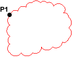 Motility the mouse to form a closed shape; the command automatically ends when a closed shape is formed.
Revision cloud finished.
You lot can apply the "Arc length" selection to control the scale of the revision cloud. This is achieved by specifying the minimum and maximum arc length. The "Object" selection is used to transform whatsoever closed shape, such every bit a polyline, spline or circle into a revision cloud.
Summit of page
The 3D Polyline Command
| Toolbar | custom | | |
| Pull-downward | |||
| Keyboard | 3DPOLY | ||
The 3D Polyline command works in exactly the same way as the Polyline command. The main difference between a normal polyline and a 3D polyline is that each vertex (selection point) of a 3D polyline can have a dissimilar value for Z (acme). In normal (second) polylines, all vertexes must have the same Z value.
3D polyline objects are non as circuitous as their 2D cousins. For example, they cannot incorporate arc segments and they cannot exist given widths. Still, they can be very useful for 3D modeling.
Command Sequence
Command: 3DPOLY
Specify beginning indicate of polyline: (selection a point)
Specify endpoint of line or [Undo]: (pick another bespeak)
Specify endpoint of line or [Disengage]: (pick a third point)
Specify endpoint of line or [Close/Disengage]: ![]() (to end, C to close or continue picking points)
(to end, C to close or continue picking points)
Notice that you are not prompted for a Z value each fourth dimension you pick a point. You must either use one of the Object Snaps to choice a point with the required Z value or use the ".XY" filter to force AutoCAD to prompt for a Z value.
Top of page
Circles, Arcs etc.
Forth with Line and Polyline, the Circumvolve command is probably one of the most frequently used. Fortunately information technology is besides one of the simplest. Still, in common with the other commands in this section in that location are a number of options that tin can help yous construct merely the circle you need. About of these options are cocky explanatory simply in some cases information technology can exist quite confusing. The Circumvolve control, for instance, offers 6 ways to create a circumvolve, while the Arc command offers ten unlike methods for drawing an arc. The sections below concentrate mainly on the default options merely feel costless to experiment.
Meridian of folio
The Circle Control
| Toolbar | Draw | | |
| Pull-down | |||
| Keyboard | CIRCLE | brusk-cut | C |
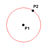
The Circle command is used to depict circles. There are a number of ways you can define the circle. The default method is to pick the eye betoken and then to either pick a second point on the circumference of the circle or enter the circumvolve radius at the keyboard.
Command Sequence
Command: CIRCLE
Specify eye point for circle or [3P/2P/Ttr (tan tan radius)]: (pick P1)
Specify radius of circle or [Bore] <50.0195>: (option P2 or enter the exact radius)
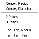 Equally you lot can encounter from the command prompt above the default options are always indicated in triangular brackets like and then <Default> and command options appear within square brackets similar so [Option]. Each option is separated by a forwards slash like this /. You can choose to use the alternative options by typing them at the prompt. For example, the circle control gives you 3 extra options to define a circle. 3P which uses whatsoever iii points on the circumference, 2P which uses 2 points on the circumference to form a bore and Ttr which stands for Tangent Tangent Radius. Obviously to use this last option you need to accept drawn two lines which you tin can use equally tangents to the circle. Try these options out to run across how they work. Note that to invoke a control choice, you lot demand merely type the upper-example part of the option name. For case, if you want to use the Ttr option, you need only enter "T". At that place are two more than circle options on the pull-down menu that enable you to draw a circle by defining the center and diameter or by using 3 tangents.
Elevation of folio
The Arc Command
| Toolbar | Draw | | |
| Pull-down | |||
| Keyboard | ARC | curt-cut | A |
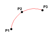 The Arc command allows you to depict an arc of a circle. At that place are numerous ways to define an arc, the default method uses iii choice points, a offset point, a 2d point and an stop point. Using this method, the drawn arc will showtime at the commencement pick betoken, pass through the second point and cease at the third point. Once yous have mastered the default method attempt some of the others. Y'all may, for example demand to describe an arc with a specific radius. All of the Arc command options are bachelor from the pull-downwards card.
Control Sequence
Control: ARC
Specify kickoff betoken of arc or [Centre]: (selection P1)
Specify second point of arc or [Middle/End]: (pick P2)
Specify stop point of arc: (option P3)
Information technology is also possible to create an arc by trimming a circle object. In practice, many arcs are really created this way. Come across the Trim command on the Modifying Objects tutorial for details.
Top of folio
The Spline Command
| Toolbar | Depict | | |
| Pull-downwards | |||
| Keyboard | SPLINE | short-cutting | SPL |
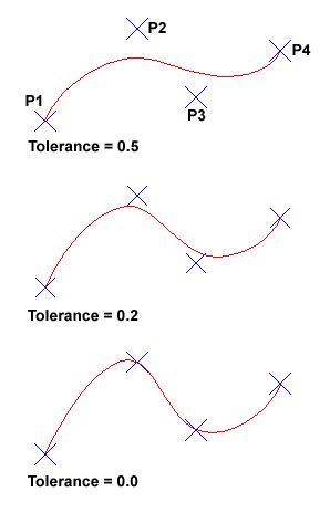 The Spline command creates a type of spline known as a nonuniform rational B-spline, NURBS for short. A spline is a smooth curve that is fitted along a number of command points. The Fit Tolerance option can be used to control how closely the spline conforms to the command points. A low tolerance value causes the spline to course close to the command points. A tolerance of 0 (aught) forces the spline to pass through the control points. The illustration on the right shows the effect of different tolerance values on a spline that is divers using the same four control points, P1, P2, P3 and P4.
Splines tin can be edited after they take been created using the SPLINEDIT control, from the pull-down menu. Using this control, you lot can change the tolerance, add more than control points move command points and shut splines, amongst other things. Even so, if you but want to move spline control points, information technology is best to use grips. Encounter the Stretching with Grips section of the Modifying Objects tutorial for details.
Command Sequence
Control: SPLINE
Specify commencement point or [Object]: (Pick P1)
Specify next point: (Pick P2)
Specify next point or [Close/Fit tolerance] <offset tangent>: (Choice P3)
Specify next bespeak or [Close/Fit tolerance] <commencement tangent>: (Pick P4)
Specify next point or [Close/Fit tolerance] <start tangent>: ![]()
Specify start tangent: (pick a signal)
Specify end tangent: (pick a point)
You tin can create linear approximations to splines past smoothing polylines with the PEDIT command, from the pull-downwards menu. However, you can too plough polylines into true splines using the Object selection of the Spline command.
Top of page
The Ellipse Control
| Toolbar | Describe | | |
| Pull-downwardly | |||
| Keyboard | ELLIPSE | short-cut | EL |
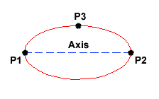 The Ellipse command gives you a number of different creation options. The default choice is to pick the two end points of an axis and and then a third point to define the eccentricity of the ellipse. Later you have mastered the default choice, try out the others.
Command Sequence
Command: ELLIPSE
Specify axis endpoint of ellipse or [Arc/Center]: (pick P1)
Specify other endpoint of axis: (selection P2)
Specify distance to other axis or [Rotation]: (pick P3)
The ellipse command tin also be used to draw isometric circles. Meet the worked example in the Drawing Aids tutorial to find out how to practise this and how to draw in isometric projection with AutoCAD.
Top of page
The Ellipse Arc Control
| Toolbar | Draw | | |
| Pull-down | |||
| Keyboard | ELLIPSE | short-cut | EL |
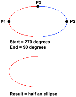 The Ellipse Arc command is very like to the Ellipse command, described in a higher place. The only difference is that, in addition to specifying the two centrality end points and the "distance to other centrality" betoken, y'all are prompted for a get-go and end angle for the arc. You may specify angles past picking points or by entering values at the command prompt. Recollect that angles are measured in an anti-clockwise direction, starting at the three o'clock position.
In truth, the Ellipse Arc control is not a new or separate command; it is just an option of the Ellipse control and it therefore has no unique control line name. It is curious why Autodesk considered this option important plenty to give it it's own button on the Draw toolbar. Still, there it is.
Command Sequence
Command: ELLIPSE
Specify centrality endpoint of ellipse or [Arc/Center]: A
Specify axis endpoint of elliptical arc or [Heart]: (option P1)
Specify other endpoint of axis: (pick P2)
Specify distance to other axis or [Rotation]: (pick P3)
Specify commencement angle or [Parameter]: 270
Specify end bending or [Parameter/Included angle]: 90
Top of page
The Region Control
| Toolbar | Draw | | |
| Pull-down | |||
| Keyboard | REGION | short-cut | REG |
A region is a surface created from objects that form a closed shape, known as a loop. The Region command is used to transform objects into regions rather than actually drawing them (i.e. yous will demand to draw the closed shape or loop first). Once a region is created, there may be niggling visual divergence to the drawing. However, if you set the shade mode to "Flat Shaded", , you will see that the region is, in fact, a surface and not but an outline. Regions are specially useful in 3D modeling because they tin be extruded.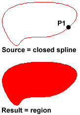
Before starting the Region command, draw a closed shape such every bit a rectangle, circumvolve or any closed polyline or spline.
Command Sequence
Command: REGION
Select objects: (Selection P1)
Select objects: ![]()
1 loop extracted.
1 Region created.
You lot can employ the boolean commands, Union, Subtract and Intersect to create complex regions.
Peak of folio
The Wipeout Command
| Toolbar | custom | | |
| Pull-down | |||
| Keyboard | WIPEOUT | ||
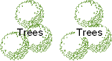
A Wipeout is an prototype blazon object. Almost commonly it is used to "mask" part of a drawing for clarity. For example, you may want to add text to a complicated office of a drawing. A Wipeout could be used to mask an expanse backside some text so that the text can easily be read, equally in the example shown on the correct.
The Wipeout command tin be used for 3 dissimilar operations. Information technology tin be used to describe a wipeout object, every bit you might await, but it can also be used to convert an existing closed polyline into a wipeout and it tin can exist used to command the visibility of wipeout frames.
Command Sequence
Command: WIPEOUT
Specify showtime signal or [Frames/Polyline] <Polyline>: (Option P1)
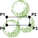 Specify next point: (Pick P2)
Specify next point or [Disengage]: (Selection P3)
Specify side by side signal or [Close/Undo]: (Pick P4)
Specify next bespeak or [Close/Undo]: ![]()
You can use as many points as you lot wish in society to create the shape you need. When y'all have picked the final betoken, employ correct-click and Enter (or hit the Enter central on the keyboard) to complete the command and create the wipeout.
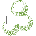
You may find that it is easier to describe a polyline commencement and so catechumen that polyline into a wipeout. To do this, start the Wipeout control then Enter to select the default "Polyline" choice. Select the polyline when prompted to do so. Remember, polylines must be airtight before they tin can be converted to wipeouts.
In most cases, you will probably want to plough off the wipeout frame.
Control Sequence
Specify starting time signal or [Frames/Polyline] <Polyline>: F (the Frames option)
Enter fashion [ON/OFF] <ON>: OFF
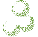 Regenerating model.
The Frames option is used to plow frames off (or on) for all wipeouts in the current drawing. You cannot control the visibility of wipeout frames individually. You should too be aware that when frames are turned off, wipeouts cannot be selected. If you need to move or alter a wipeout, y'all need to have frames turned on.
It is often more convenient to draw the wipeout later on the text so that you can see how much space you need. In such a instance, y'all may need to employ the DRAWORDER control () to strength the text to announced above the wipeout.
Tip: If you have the Express Tools loaded, you can apply the very useful TEXTMASK command, which automatically creates a wipeout below whatever selected text. Find it on your pull-down at
Peak of folio
Points and Signal Styles
Points are very simple objects and the process of creating them is too very simple. Points are rarely used as drawing components although there is no reason why they could non be. They are normally used but every bit cartoon aids in a similar style that Construction Lines and Rays are used. For instance, points are automatically created when yous use the Mensurate and Divide commands to set out distances along a line.
When adding points to a drawing information technology is normally desirable to prepare the point way first because the default style can be difficult to see.
Top of page
The Point Control
| Toolbar | Draw | | |
| Pull-down | |||
| Keyboard | Indicate | short-cut | PO |
The point command will insert a point marker in your drawing at a position which you option in the drawing window or at any according location which y'all enter at the keyboard. The default bespeak style is a elementary dot, which is often difficult to see merely you can change the point mode to something more easily visible or elaborate using the indicate style dialogue box. Points tin can exist used for "setting out" a drawing in add-on to construction lines. You can Snap to points using the Node object snap. See the Object Snap tutorial for details.
Command Sequence
Command: Point
Current point modes: PDMODE=0 PDSIZE=0.0000
Specify a point: (selection whatsoever point)
Strangely, in Multiple Point mode (the default for the Bespeak push on the Draw toolbar) you will demand to use the escape key (Esc) on your keyboard to end the control. The usual right-click or enter doesn't work.
Peak of folio
The Point Manner Command
| Toolbar | none |
| Pull-downward | |
| Keyboard | DDPTYPE |
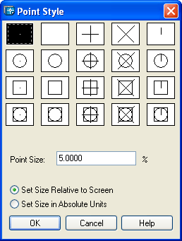
You tin beginning the point style command from the keyboard by typing DDPTYPE or you can showtime it from the pull-down bill of fare at The command starts by displaying a dialogue box offering a number of options.
To change the point style, just pick the picture of the style you lot desire and then click the "OK" push button. You will need to apply the Regen command, REGEN at the keyboard or from the pull-downwards to strength any existing points in your drawing to display in the new way. Any new points created afterward the way has been set will automatically brandish in the new style.
One interesting aspect of points is that their size tin can exist set to an accented value or relative to the screen size, expressed as a per centum. The default is for points to display relative to the screen size, which is very useful because it means that points volition remain the aforementioned size, irrespective of zoom gene. This is particularly convenient when drawings get complex and the drawing process requires a lot of zooming in and out.
Acme of page
Multilines
Multilines are circuitous lines that consist of betwixt 1 and 16 parallel lines, known as elements. The default multiline style has only 2 elements but you tin create additional styles of an almost countless variety. The Multiline Manner command enables you to create new multiline styles by calculation line elements, changing the colour and linetype of elements, adding terminate caps and the choice of displaying as a solid colour.
Pinnacle of page
The Multiline Command
| Toolbar | custom | | |
| Pull-downwards | |||
| Keyboard | MLINE | brusque-cut | ML |
The Multiline command is used to draw multilines. This process of drawing is pretty much the same equally drawing polylines, additional line segments are added to the multiline as points are picked. As with polylines, points can be unpicked with the Undo option and multilines tin can be closed.
When you start the Multiline command you lot too have the selection to specify the Justification, Scale and Style of the multiline. The Justification option allows you to prepare the justification to "Peak", the default, "Zero" or "Bottom". When justification is set to top, the meridian of the multiline is drawn through the pick points, as in the illustration below. Nix justification draws the centreline of the multiline through the pick points and Bottom draws the lesser line through the choice points. Justification allows you lot to control how the multiline is drawn relative to your setting out information. For example, if you are cartoon a new road with reference to its centre line, so Zero justification would exist appropriate.
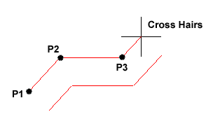 The Scale option allows you to set a scale factor, which effectively changes the width of the multiline. The default calibration factor is set to one.0 so to half the width of the multiline, a value of 0.v would be entered. A value of 2.0 would double the width.
The Style option enables yous to set the current multiline style. The default way is called "Standard". This is the only style available unless y'all have previously created a new mode with the Multiline Way command. Follow the command sequence below to meet how the Multiline command works then endeavor changing the Justification and Calibration options.
Command Sequence
Command: MLINE
Current settings: Justification = Top, Scale = 20.00, Style = STANDARD
Specify start signal or [Justification/Calibration/STyle]: (Pick P1)
Specify adjacent point: (Pick P2)
Specify next point or [Disengage]: (Pick P3)
Specify next point or [Close/Undo]: ![]() (to end or continue picking or C to close)
(to end or continue picking or C to close)
Summit of page
The Multiline Way Command
| Toolbar | none |
| Pull-down | |
| Keyboard | MLSTYLE |
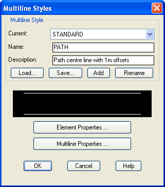
The Multiline style control is used to create new multiline styles, which can and then be used with the Multiline command. When you lot start the command for the first time, you will see the Multiline Styles dialogue box indicating that the Standard way is "Current". To create a new manner, enter a new fashion name in the "Proper noun" edit box by overwriting "STANDARD" and enter an optional clarification in the "Description" edit box. The dialogue box should now look something like the one on the right. When you are happy with the new proper name and description, simply click on the "Add" push. Your new style will now announced in the "Current" box. The new style y'all accept created is just a re-create of the Standard style, and so the next step is to alter the style to arrange your own purposes. Click on the "Element Properties…" push button to proceed.
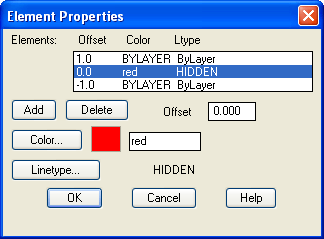 You volition now run into the Chemical element Properties dialogue box appear. This dialogue box allows yous to add new line elements or delete existing ones and to command the chemical element offset, colour and linetype. Click the "Add" button to add a new chemical element. A new line element now appears with an offset of 0.0, in other words, this is a eye line. Highlight the pinnacle element in the "Elements" list and change the offset to 1.0 past entering this value in the "Offset" edit box. Now exercise the same with the bottom element remembering to enter a value of -1.0 because this is a negative starting time. You now have a multiline that is ii drawing units wide with a centre line. Permit's now change the colour and linetype of the heart line.
Highlight the 0.0 offset element by clicking it in the "Elements" list. To change the colour, just click on the Colour… push and select an appropriate colour from the palette. When a colour has been selected, click the "OK" button on the palette to return to the Element Backdrop dialogue box.
Irresolute the linetype is a little more complicated considering we will need to load the required linetype kickoff. However, click on the "Linetype…" button to continue.
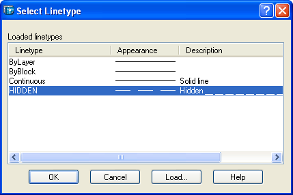
The Select Linetype dialogue box appears with just a few solid linetypes listed, ByLayer, ByBlock and Continuous. Click on the "Load…" button. The Load or Reload Linetypes dialogue box now appears. Ringlet down the list of linetypes until you find ane chosen "Subconscious". Highlight Hidden and and so click the "OK" push button. Yous will at present see the Subconscious linetype appear in the "Loaded linetypes" listing in the Select Linetype dialogue box, which should at present look similar to the 1 shown above. Finally, highlight Hidden and click the "OK" button. Your Element Backdrop dialogue box should now expect like to the one in the illustration in a higher place. To complete our new fashion, we will add some end caps and a solid fill. Click on the "Multiline Properties…" push to go on.
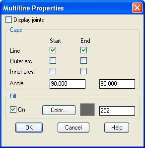 In the Multiline Backdrop dialogue box, click in the "Line" check boxes under "Beginning" and "End". This will accept the effect of capping the ends of the multiline with a xc caste line. As y'all tin can encounter from the dialogue box, you can alter this angle if yous wish to give a chamfered end. Adjacent, click the "On" check box in the "Fill up" section and and then click on the Colour… push button and select the fill colour from the palette. The Multiline Properties dialogue box should now look similar the one in the illustration on the left. Finally, click the "OK" button in the Multiline Properties dialogue box and again in the Multiline Mode dialogue box. You are now set to draw with your new multiline.
Commencement the Multiline command, pick a number of points and admire your handiwork. If you have followed this tutorial closely, your new multiline should look something like the one in the illustration on the correct. Notice the effect of the various changes you take made compared with the Standard multiline mode.
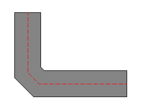 One limitation of multiline styles is that you cannot modify a style if there are multilines referencing the style in the current drawing. This is a shame because it means that it is not possible to update multiline styles in the aforementioned mode as it is possible to update text or dimension styles. You too cannot modify the style of an existing multiline. If you really desire to modify a multiline way, yous will have to erase all multilines that reference the manner commencement.
If you are new to AutoCAD, the whole process of working with multilines and creating multiline styles may appear a little bewildering considering it touches upon a number of aspects of the program with which y'all may not exist familiar. If this is the case, it may exist a practiced idea to render to this tutorial in the future. Multilines are useful because they tin save lots of time but their use is fairly specific and you should think advisedly before using them. It may, for example, exist more convenient simply to draw a polyline and to create offsets using the Showtime command.
Elevation of folio
Tips & Tricks

Command Sequence
Command: LINE
Specify first signal: (pick P1)
Specify next point or [Undo]: (choice P2)
Specify next point or [Undo]: (correct-click and select Enter)
Command: (right-click and select Echo Line)
Specify offset indicate: (choice P1)
Specify side by side betoken or [Disengage]: (pick P2)
Specify next betoken or [Undo]: (right-click and select Enter)
Command: (right-click and select Repeat Line)…
You could keep this cycle as long as you needed, using only the mouse for input.
- You can modify the Linetype of any of the objects created in the above tutorial. By default all lines are fatigued with a linetype called "Continuous". This displays equally a solid line. Withal, lines tin exist displayed with a dash, nuance-dot and a whole range of variations. Run into the Object Properties tutorial for details.
Top of page
Donate to CADTutor
If you found this tutorial useful, y'all might like to consider making a donation. All content on this site is provided costless of charge and we promise to go along information technology that way. Nonetheless, running a site like CADTutor does toll money and yous tin can help to better the service and to guarantee its futurity by altruistic a pocket-size amount. We guess that you probably wouldn't miss $5.00 merely it would brand all the difference to united states of america.
mcclendonthavends.blogspot.com
Source: https://www.cadtutor.net/tutorials/autocad/drawing-objects.php
0 Response to "autocad 3d drawing in tamil"
Post a Comment